Knight
Rider Circuit
Today we are
going to create a simple knight rider circuit in two ways. Before the coding
part let’s create the circuit using proteus. If you are not much familiar with
proteus and MPLAB you can view my first post on embedded system.
This is the screen
shot of the circuit, when you switch on the push button knight rider circuit
will start to work.
 |
| figure - 01 |
I am gonna program
this in two ways. First let’s see the long and descriptive method of doing that.

 |
| figure - 02 |
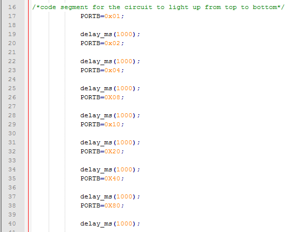
If I briefly
explain the things above, I have used a delay function to make a delay in
between two bulbs blink and the response for the selected delay will depend on
your machine processor. That means delay_ms(1000) ;will behave differently
in different machines, so you can adjust it according to your requirement.
Now you may wonder what’s meant by PORTB =
0x01, that simply used to select which bulb should light up at the moment. Easier
way to do this is use online binary to hexadecimal converter. (http://www.binaryhexconverter.com/binary-to-hex-converter
)
We can represent above 8 bulbs in a binary
representation
If you need to light up 6 th bulb,
the binary representation and hexadecimal representation should look like
below.
 |
| figure - 03 |
So inside the program we can write it as
POARTB = 0x020;
This is the second and short way of doing that,
Just replace your while loop by using following code,
 |
| figure - 04 |
Good luck! :)
niyamai akka
ReplyDeleteIt's very helpful for me. .. plz add more about 7 segment anode cathode display. ..
ReplyDelete