How to create a simple application using
Proteus ISIS and MPLAB
First open MPLAB IDE, go to project ->Project Wizard and go through following process.
 |
| figure - 01 |
 |
| figure - 02 |
Then select the
device, in my case I select the PIC16F84A.
 |
| figure - 03 |
Now you need to
select a language toolsuite. Select HI TECH Universal Toolsuite from the Active
Toolsuit drop down list.
 |
| figure - 03 |
In any case if the language toolsuit HI-TECH
toolsuit is
not visible just go to the select language toolsuit in project and add it.
 |
| figure - 04 |
 |
| figure - 05 |
 |
| figure - 06 |
|
|
|
|
|
|
|
Then browse the location for the project.
 |
| figure - 07 |
 |
| figure - 07 |
 |
| figure - 08 |
 |
| figure - 09 |
 |
| figure - 10 |
At the end of the project wizard you will get the below output.
 |
| figure - 11 |
Now you need to add a new file to the project, to do that, go to
file ->Add New file to project and create a c file.
 |
| figure - 12 |
 |
| figure - 13 |
Then you will get the below window.
 |
| figure - 14 |
| Now you can give instructions to your microcontroller using your project1.c file. Let’s write a simple c program for the PIC we selected earlier (PIC16F84A). |
|
 |
| figure - 15 |
Before going deep in code let’s have an idea
about our micro-controller, Open proteus ISIS and click on component model.
 |
| figure - 16 |
Then click on the letter P to
pick a device.
 |
| figure - 17 |
It will show you the below window.
 |
| figure - 18 |
After selecting
the micro-controller click on OK button. Then it will show you the micro-controller
which we are going to program.
 |
| figure - 19 |
First click on
it and then click on the program board.
 |
| figure - 20 |
Now we are
going to add a LED into our circuit, I just type LED in keyword box and select animated
led in any color you wish, red, green and blue.
 |
| figure - 21 |
 |
| figure - 22 |
Now we need to add a power terminal to the circuit.
So to do that click on Terminals Mode.
 |
| figure - 23 |
Then select the power terminal and place it
on the circuit board.(Also add ground terminal to the circuit). After you place
the terminal don’t forget to right click on your mouse. If not terminals will
be placed everywhere :D.
 |
| figure - 24 |
Now our circuit board will looks like below.
 |
| figure - 25 |
Now draw lines
(connect wires) and complete the circuit.
 |
| figure - 26 |
 |
| figure - 27 |
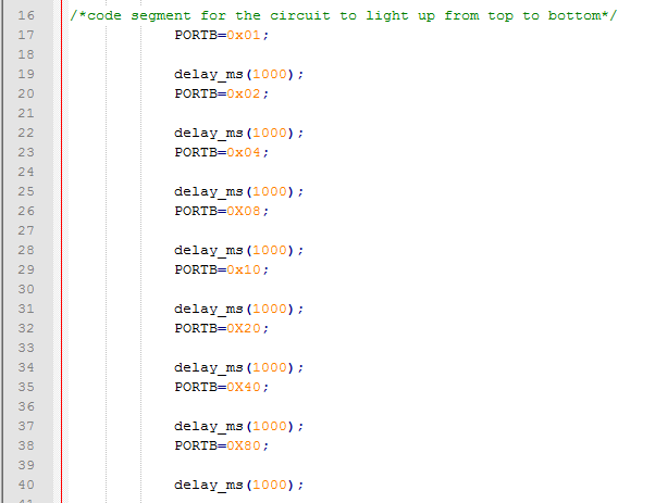
Now the time to write our codes. So let’s move
on to the MPLAB IDE
 |
| figure - 28 |
We going to define all A ports as inputs and
all B ports as outputs by giving them 1 (input) and 0(output). Now I need to
give power to the LED. To do that I gave 5v to the diode by making RB0=1. Click
on the red color button to build with compile our program.
 |
| figure - 29 |
 |
| figure - 30 |
Now we need to load our instructions (Program)
to the micro-controller. Double click on the micro-controller.
 |
| figure - 32 |
Click on the folder
mark and load the hex file.
 |
| figure - 33 |
Now run your
circuit by clicking on the run button which is located in the left bottom
corner of the proteus ISIS.
 |
| figure - 34 |
Enjoy your codes.
Output will definitely looks like below.
 |
| figure - 35 |
Don’t forget to
stop the application if you need to do any changes to the circuit.
Will meet u all
with Knight Rider circuit soon..