How
to Create a Simple Digital Clock Using PIC16F877A
Hello friends today we
are going to create a simple digital clock using PIC 16F877A microcontroller.
As the first step you need to arrange your circuit as below. If you have any
doubt in designing circuits using proteus you can view my previous posts :).
 |
| figure - 01 |
Let’s try to understand
the code below. Here is the content of my clock.c.
 |
| figure - 02 |
As you can see I have declare 6 variables globally and I have used delay function to control the speed of my clock. In future steps you will understand the mean of above variables.


 |
| figure - 03 |
For
your conventions I have arrange the code in right order but I will explain the
code from the main function. In my main function (void main ( )) I have
define my B, C, D ports as outputs as they become the input of my clock. So
from that point you will understand we need to control the signal which is
generated from port B, C & D. Also I have define A ports as the inputs
for the microcontroller, So if you need to add any controls (Switches) for the
circuit you can use them.
As
you can see inside my main function I am calling to a function call clock().Inside
the void clock function there is another function call hours Is
it too messy J .Let
see the arrangement of my function calls .
 |
| figure - 04 |
As
all of you can see I have used 6 binary coded decimal 7 segment displays to
implement my clock, two of them for representing hours, two for minutes and
another two for representing seconds. If I concern about my seconds ()
function there I need to control two seven segment displays to show numbers
from 0-59 .All of the 8 ports of these two seven segment displays are connected
to the RD ports of the microcontroller. RD4-RD7 should display the numbers from
0-5 and RD0-RD3 should display the numbers from 0-9.It not too hard so don’t messed
up okayJ.
To
achieve above goal I have simple declare a global array call power[ ] which
contains {0,16,32,48,64,80}.For the simplicity let’s convert these numbers into
binary .
 |
| figure - 05 |
I
think now you get the idea 0, 16,32,48,64 & 80 will help you to display the
numbers from 0-5 in the red colored seven segment display.
 |
| figure - 06 |
Then
you may wonder how to display numbers from 0-9.
 |
| figure - 07 |
Let
think what will happen if I add 1 to 16, It will give 17 and its binary
representation will look 00010001. if I
add 1 to 17 it gives 18 and binary representation is 00010010.Everything in
brief J
 |
| figure - 08 |
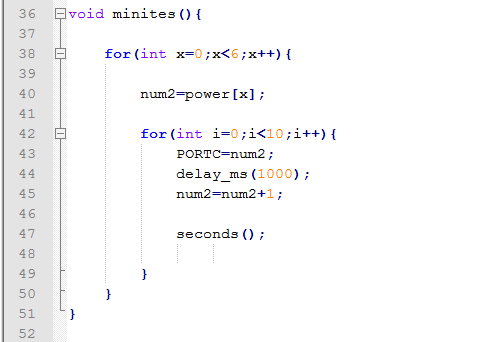
There
is no more big logics, other parts are only contains for loops to manage the
continuity of the process. minutes () seconds () and hours ()functions
are completely working in the same manner. If there is any geek who is willing
to add switches to this circuit,
you can share your code with us J.